Click or tap image to expand
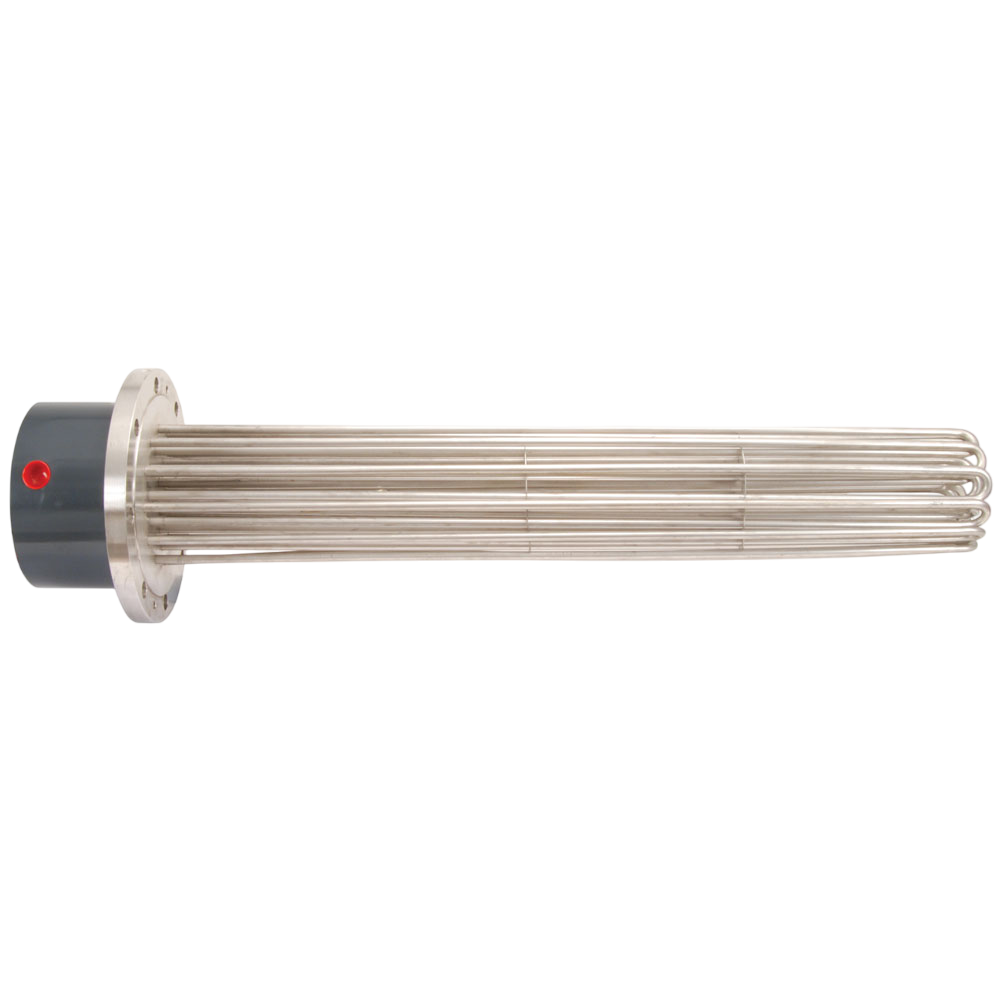
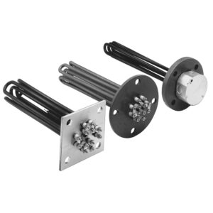
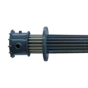
Pressure Rated Flanged Immersion Heaters
Mounting Options
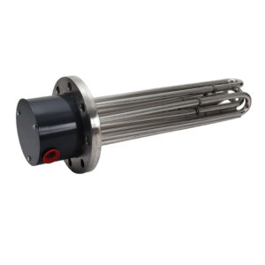
Round Mounting Flange
Standard ASTM Pressure-Rated Flange Sizes: 3, 4, 5, 6, 8, 10, 12, 14
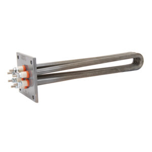
Square/Rectangular Mounting Flange
Custom Manufactured to meet application needs.
Flange Materials
304 SS Flange
A Chromium (18-20%), Nickel (8-11%), Iron Alloy used in the food industry, sterilizing solutions, air heating and many organic and inorganic chemicals.
304L SS Flange
A Chromium (18-20%), Nickel (8-11%), Low Carbon Iron Alloy used in the food industry, sterilizing solutions, air heating and many organic and inorganic chemicals.
316L SS Flange
A Chromium (16-18%), Nickel (11-14%), Low Carbon Iron Alloy with Molybdenum (2-3%) added to improve corrosion resistance in certain environments, especially those that would tend to cause pitting due to the presence of chlorides. Applications include deionized water.
Steel Flange
Low Carbon Steel: Applications include fluid heat transfer media, tar, high to low viscosity petroleum oils, asphalt, wax, molten salt, and other solutions not corrosive to a steel sheath.
Electrical Terminations
Type 1N Terminal Box
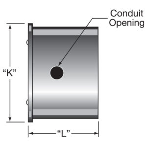
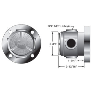
NEMA 1 rating For heaters having no thermostat Supplied with all Preconfigured and Stock Heaters All flange sizes See Learn More for flange sizes and measurements
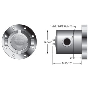
Type 1T Terminal Box
NEMA 1 rating For heaters with thermostat Supplied with all Preconfigured and Stock Heaters All flange sizes See Learn More for flange sizes and measurements
Type 2N Terminal Box
NEMA 4 rating For heaters having no thermostat 3 inch flanges Requires the use of the cover gasket
Type 2T Terminal Box
NEMA 4 rating For heaters with thermostat 3 inch flanges Requires the use of the cover gasket
Type 3N Terminal Box
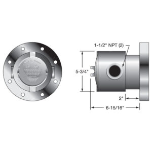
NEMA 4 rating For heaters having no thermostat 4 and 5 inch flanges Requires the use of the cover gasket
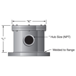
Type 3T Terminal Box
NEMA 4 rating For heaters with thermostat 4 and 5 inch flanges Requires the use of the cover gasket
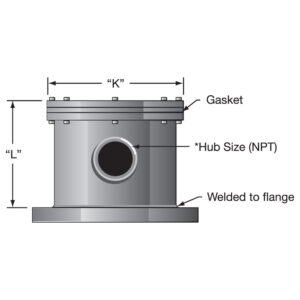
Type 4N Terminal Box
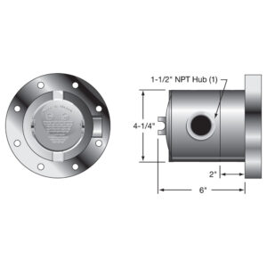
NEMA 4 rating For heaters having no thermostat 6 through 14 inch flanges See Learn More for flange sizes and measurements
Type 4T Terminal Box
NEMA 4 rating For heaters with thermostat 6 through 14 inch flanges See Learn More for flange sizes and measurements
Type 5N Terminal Box
NEMA 7 rating For heaters having no thermostat 6 through 14 inch flanges See Learn More for flange sizes and measurements.
Type 5T Terminal Box
NEMA 7 housing For heaters with thermostat 6 through 14 inch flanges See Learn More for flange sizes and measurements
Thermostats
DPST Thermostat
Double Pole – Single Throw Thermostats: Style B, Style C
SPST Thermostat
Single Pole – Single Throw Thermostats: Style A, Style D, Style F
Request Other Thermostat
If your filter selections do not return your desired results from our standard configurations, please continue to select your Specifications. When you are finished, save your selections in the Wish List (using the button at the right of this page) and follow the steps to submit them to Tempco.
Thermostat Options
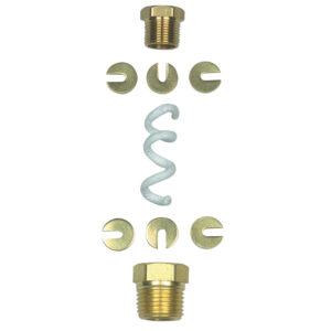
Stuffing Box Assembly
The Stuffing Box Assembly is used to seal the thermostat capillary when the sensing bulb (3/8″ max. OD) is immersed directly in a liquid rather than in a thermowell. The Stuffing Box consists of six slotted washers used to compress a graphite packing into a 3/8″ NPT male pipe thread fitting. Assembly Instructions Feed sensing bulb through hole in upper and lower fitting. Insert washers and packing into top cavity of lower fitting. Upper fitting then screws into lower fitting, creating the seal. Part Number: TST-109-101
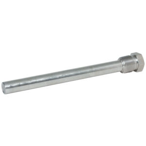
Thermowells
Stainless Steel or Plain Steel: Thermowells provide protection for bulb and capillary sensors. They are supplied with a 1/2″ NPT male thread for mounting and a 3/8″ NPT internal thread that can be used with the stuffing box assembly to secure the capillary to the well. ID: 0.50″, OD: 0.56
Heater Options
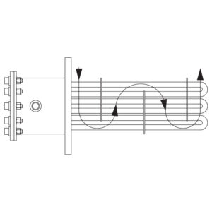
Flow Control Baffles
For flange heaters used in circulation tanks, to aid heat transfer by forcing the liquid or gas back and forth across the elements. Baffles can be custom designed and positioned for your application.
Terminal Housing Standoff
The electrical housing is separated from the flange by an air gap (six-inch standard) to lower the ambient temperature of the electrical wiring. This option is used on flanged immersion heaters where the flange temperature exceeds 482°F (250°C).